A type of welding that is generally limited to thin materials high-integrity joints or small parts because of its low welding speed and high cost of equipment and materials. Welding Principles and Applications Fifth Edition Larry Jeffus Australia Canada Mexico Singapore Spain United Kingdom United States.

Welding Symbols With Figures Paktechpoint
An included weld angle or root opening that is too narrow promotes the formation of a concave weld bead that places the weld surface in tension and promotes solidification cracking in the weld metal.
. One of the most important welding symbols is the fillet weld. Be creative and detailed on your drawings. This chapter describes the fundamentals of weld joint design including the parameters that are obtained after designing a weld joint.
Contract design drawings shall specify the effective weld length and for partial. Basic Types of Welds. Resistance spot weld symbols shall be centered on the reference line.
CHAPTER 24 GLASS AND GLAZING. 21 2022 at 1159pm. Up to 24 cash back Welding Process Major effect on selection of joint design Each welding process has characteristics that affect its performance Some processes are easily used in any position Others may be restricted to one or more positions Rate of travel penetration deposition rate and heat input also affect welds.
Your assignment this week is to draw out welds on plates using 6010 and 7018 rods in different positions. Welding Symbols Welding symbols are defined by the American Welding Society in ANSIAWS A24 Standard Symbols for Welding Brazing and. Learn vocabulary terms and more with flashcards games and other study tools.
American Welding Society- CWI Welding Inspection Technology Chapter Examination 2008 146 Terms. Different groove designs should have a distinct symbol to minimize the chance of making a mistake. Dimensions may be shown on either side of the reference line.
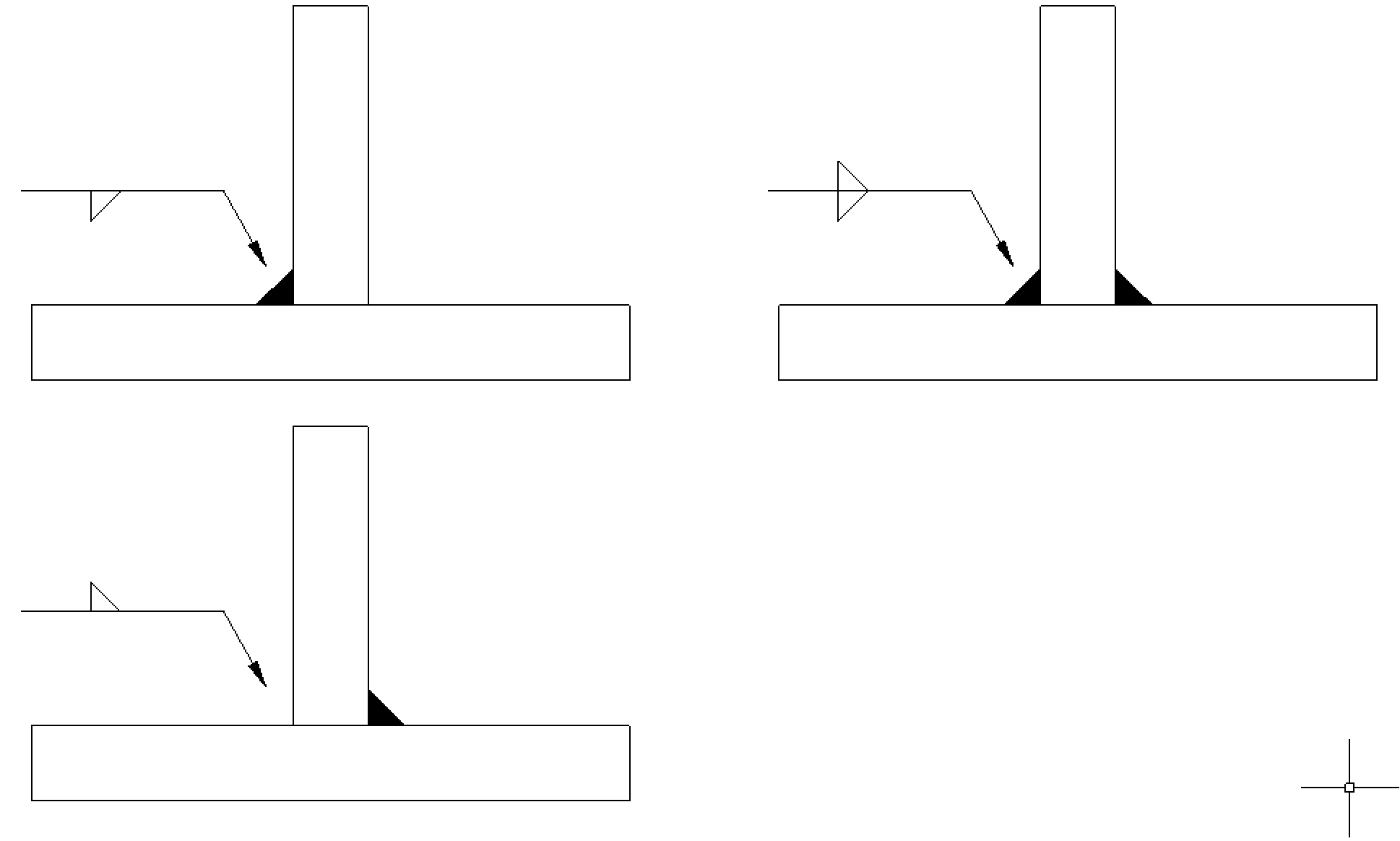
A T joint is a joint where two metal plates are at a 90 degree angle and one of the pieces connects away from the edge. 96 F y produces tension throughout the weld F x produces shear throughout the weld M produces a bending stress in the welds with tension at A and compression at C Therefore. Label the parts or areas of a grooved butt weld and a fillet weld.
11822 12122 Drawings are due on Friday Jan. The COTP may require that the operator of the facility notify the COTP before any welding or hot work operations are conducted. Locate and apply required weld and joint information from an AWS welding symbol.
Variations such as grooving the welded metal and using an open corner joint instead of a closed corner joint. The joint design should allow for the first weld bead to be deposited with a convex surface. S ut 400MPa S y 220MPa 1 Factor of safety guarding against static yielding in.
3-3 have no arrow or other side significance in themselves although supplementary symbols used in con-junction with them may have such significance. 21 2022 at 1159pm. Identify and describe the various welds that may be used in each welding joint.
The bracket material is. 20 Full PDFs related to this paper. Fillet weld V-groove X-groove U-groove I-groove is just a few of many.
Chapter 18 Activity. A short summary of this paper. About Press Copyright Contact us Creators Advertise Developers Terms Privacy Policy Safety How YouTube works Test new features Press Copyright Contact us Creators.
This groundbreaking new text offers a complete hands-on guide to professional welding and fabrication from print reading through invoicing via small material-conserving projects that hone essential welding skills while allowing students to be creative making exercises both practical and personaland avoiding the tedium of traditional repetitive welding practices. There are three basic types of welds. The joint design selected will of course dictate what type of weld is to be made.
Additionally weld penetration is significantly less. Chapter 1- The Welding Inspector 6 Terms. 223 Weld Size and Length.
A lap joint is where one plate lays on top of another plate. Log in Sign up. Drawings of those joints or groups of joints in which it is especially impor-tant that the welding sequence and technique be carefully controlled to minimize shrinkage stresses and distortion shall be so noted.
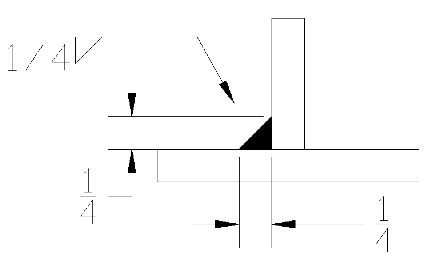
Size of Resistance Spot Welds. Plug and slot welds Other types of welds include. Fillet welds are generally performed on a 90 degree joint of 2 perpendicular pieces of metal.
The welded joint will occur at the edge of the top plate. Welding and Metal Fabrication. Welding Joint Design Welding Symbols and Fabrication.
3rd Quarter - Semester 2. Various processes involved in fabrication of the prototype model are as under. Welding Symbols Arrow side of a joint is the line side area or near member to which the arrow points The side opposite the arrow side is the other side Shape of weld is shown with the symbols below Shigleys Mechanical Engineering Design Fig.
F x 5340cos30 46246N F y 5340sin30 2670 N M 534000095 5073Nm From Table A-20. This weld is an extremely common practice in fabrication and field work. To minimize the occurrence of these defects a little variation can be applied.
Modes of failure rigidity and stiffness loading condition welding symbol type of weld and weld joint 221 Introduction Weld joints may be subjected to variety of loads ranging from a simple tensile. Sketch a weld on plates in the 1G and 1F positions. Learning Objectives After studying this chapter you will be able to.
In addition some symbol also represents a different type of welding process in figure 3 displays the most. Welding Joint Design Welding Symbols and Fabrication. Welding symbols and their components are created using the same units the drawing in which they are displayed.
As we know there is just so much groove design in welding. JS11 Joint Design Welding Symbols Student Handout for. ButtThis is a joint where two plates are butted together edge to edge.
Start studying Welding Joint Design and Welding Symbols. Arc spot and seam welds Edge welds Flange welds Surfacing welds Seal welds. 11822 12122 Drawings are due on Friday Jan.
RCSC - Specification for Structural Joints Using ASTM A325 or. Identify the five basic welding joints. Types of welding defects associated with the corner joint are lamellar tearing incomplete penetration porosity slag inclusion etc.
529606 Reserved 529607 Fasteners. Up to 24 cash back The correct joint design will then need a weld deposited to the highest quality possible at the lowest possible cost. Resistance spot weld symbols fig.
This symbol is characterized by a right triangle which is the lateral shape of a real fillet weld. 222 Joint Welding Sequence. Full PDF Package Download Full PDF Package.
Similar to tee joints.

Pin On Welding

Chapter 6 Welding Techniques Roadkill Customs Welding Rat Rod Chapter
Weld And Welding Symbols Plasma Welding Welding Positions Welding Machines And Other Weliding Cutting Systems Plasma Welding

Understanding Welding Symbols American Welding Society Education Online

Weld Positions Joints In 2020 Welding Welding Table Positivity
Fillet Weld Symbols Interpretation Of Metal Fab Drawings
Weld Joints And Weld Types Goodheart
Fillet Weld Symbols Interpretation Of Metal Fab Drawings
0 comments
Post a Comment